
Understanding how a wheel balancer measures imbalance decides whether a tire or repair shop turns predictable profit or burns labor hours chasing phantom vibrations. When a technician does not grasp how the machine turns raw centrifugal force into correction data, small geometry errors pass straight through to residual steering shake and costly customer comebacks.
This breakdown maps the full measurement cycle: how centrifugal force is detected during a spin, how the machine resolves that signal into a correction weight and position through two-plane geometry, and how you can verify a unit’s accuracy for your own bays. It is a working-principle guide; for model selection and specifications, see our companion on choosing the best wheel balancer for your shop.
What Does a Wheel Balancer Actually Measure?
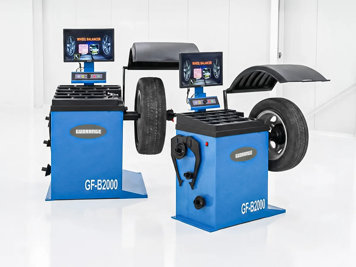
A wheel balancer measures the centrifugal force a spinning wheel produces and converts it into a correction weight and position. Higher-end units also read rim geometry and road-force variation to surface vibration sources that a weight-only balance would miss.
Mass Imbalance and Centrifugal Forces
Wheel balancers detect uneven weight distribution around the rotation axis by measuring the centrifugal force generated as the tire spins. The machine captures the resulting force pattern and translates it into a correction magnitude and angular location.
From these force signals the control system derives two outputs: how much correction mass to add, and at which angular position on the rim to place it. Two measurement modes cover most jobs:
- Dynamic balancing: Measures forces across two planes, typically the inner and outer rim edges, to correct side-to-side wobble.
- Static balancing: Tracks single-plane radial force to address basic vertical wheel hop.
Rim Dimensions and Road Force Variations
To convert raw vibration data into usable weight placement, technicians enter three geometric measurements into the machine: the distance to the inner rim edge, the rim diameter, and the rim width. The balancer relies on these dimensions to map the measured force vectors to physical attachment points on the wheel.
Advanced road-force balancers take the process further to diagnose complex ride-quality issues. These machines press a powered roller against the spinning tread to simulate a loaded driving contact patch, then measure how the radial force between tire and drum fluctuates over one revolution. That fluctuation is radial force variation (RFV)—a property defined by ASTM F1806—and it identifies stiff or soft spots in the tire casing independent of weight distribution. Separating RFV from mass imbalance lets a technician diagnose ride complaints that no amount of correction weight can fix.
What Happens When the Wheel Spins?
The spin cycle turns rotation into data. Force sensors measure the imbalance while a position encoder tracks angular location, so the machine can calculate the correction weight and where it belongs for static and dynamic imbalance.
Measuring Physical Forces and Vibrations
The balancer accelerates the assembly to a controlled speed, generating enough centrifugal force to make even small mass offsets measurable. Uneven mass distribution pulls the wheel away from its true center of rotation, producing a periodic force that is transmitted through the shaft into the machine frame.
Force transducers mounted in the frame beside the spindle bearings detect the oscillating loads created by the heavy spot as the wheel rotates. A position encoder simultaneously tracks angular timing, so each force peak can be linked to a specific clock position on the rim.
During the active spin, the machine separates the two motions: static imbalance, which causes vertical bouncing, and dynamic imbalance, which creates a side-to-side wobble across the inner and outer wheel planes.
Calculating Weight Adjustments
The balancer’s control system combines the live sensor data with the entered wheel geometry, specifically rim diameter and width. The software uses this combined data to calculate the correction weight required to offset the imbalance.
Once the spin stops, the system displays the required mass for both the inner and outer planes, then uses a digital screen or LED guide to point the technician to the rotational position where the corrective weights belong.
Technicians run a final verification spin after applying the weights. This confirms the residual imbalance has dropped to an acceptable level, so the wheel rides smoothly for the customer.
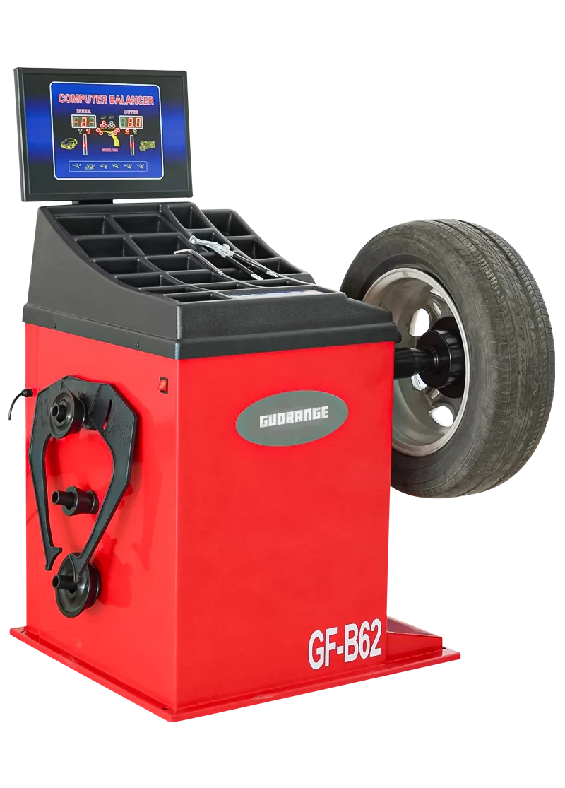
How Does the Machine Calculate Weight and Position?
The microprocessor combines sensor-detected vibration forces with the wheel’s physical dimensions to find the mass and angular location needed for the inner and outer correction planes.
| Data Input | Hardware Source | Role in Calculation |
|---|---|---|
| Vibration Amplitude | Force Sensors | Determines the mass of the required counterweight. |
| Phase Angle | Position Encoder | Identifies the clock position for weight placement. |
| Wheel Geometry | Gauges / Scanners | Defines correction radii and separates the inner and outer planes. |
Detecting Imbalance Forces and Rotation Angles
Once the transducers produce analog force signals and the encoder supplies angular reference, the control system converts them into a numerical correction plan through four processing stages:
- Signal digitization: An analog-to-digital converter turns raw force voltages into clean digital samples for each revolution.
- Phase extraction: Encoder pulses mark the angular position of each force peak, giving a stable clock reference for the heavy spot.
- Vector resolution: The microprocessor separates radial (vertical) from lateral (sideways) components and allocates them to the inner and outer correction planes.
- Weight calculation: Force at a known radius is divided by the effective lever arm to produce the required counterweight mass and its clock position.
Mapping Sensor Data to Wheel Geometry
Force data alone cannot tell a technician where to attach a weight. The microprocessor must map the measured vibration vectors to the physical rim using the wheel’s geometry. Without this step, the machine computes a correct mass but assigns it to the wrong coordinates, leaving persistent vibration.
- Geometric modeling: The balancer uses three core dimensions—distance, diameter, and rim width—to build a spatial model and define the inner and outer correction planes.
- Dynamic equations: Internal software solves two-plane balancing equations to address both the vertical shake and the side-to-side couple.
- Mass conversion: The system applies calibrated constants to convert the raw sensor signal into the counterweight mass required at a given rim radius.
- Pattern optimization: Advanced models use rim-contour scanning to match wheel profiles against stored patterns, placing weights behind spokes or on adhesive zones.
What Is the Difference Between Static and Dynamic Imbalance?
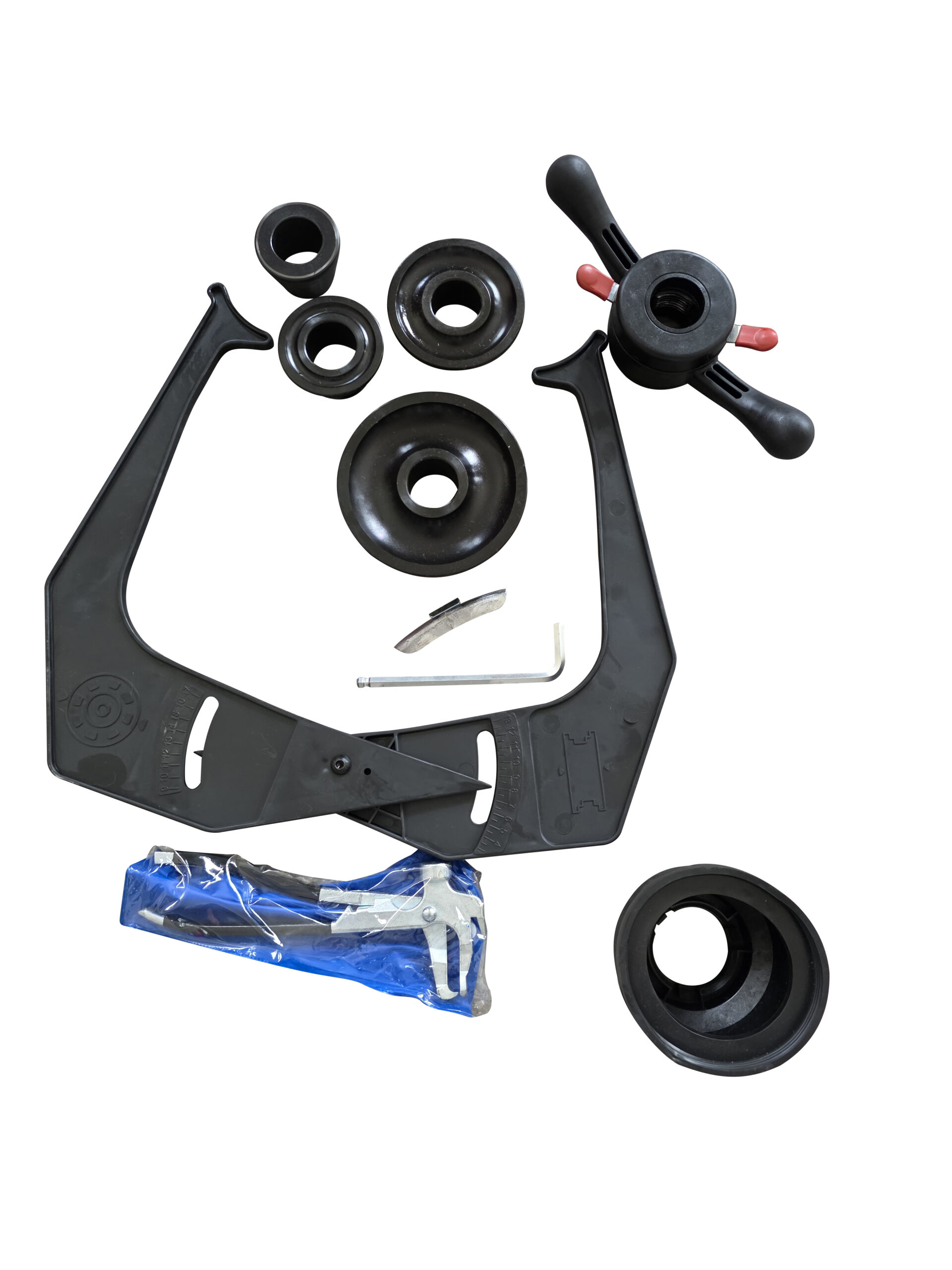
Static imbalance means the wheel’s center of mass does not sit on its axis of rotation, producing a net radial force felt as vertical hop. Dynamic imbalance means mass is unequal across the wheel’s width, creating a moment that tilts the assembly side-to-side. Correcting both requires two independent correction planes.
Static Imbalance and Single-Plane Vibration
Static imbalance exists when the center of mass is offset from the rotational axis. The heavy side generates a net radial force during every revolution, causing the wheel to bounce vertically against the road surface. Drivers feel this as up-and-down vibration through the floor or seat. The condition can also be detected on a stationary bubble balancer where gravity swings the heavy spot to the lowest point. A single correction weight placed opposite the heavy spot cancels the offset and is sufficient for narrow wheels—motorcycle or trailer tires, for example—where width does not introduce a second-plane moment.
Dynamic Imbalance and Dual-Plane Couple
Dynamic imbalance occurs when unequal mass on the inner and outer rim planes creates a rotational couple—a tilting moment about the wheel’s center—even if the overall center of mass sits on the axis. The wheel generates alternating side forces every revolution, felt as side-to-side wobble or steering shimmy at speed. Because the disturbance is a moment rather than a single radial force, correcting it requires two independent weight planes (inner and outer) to cancel both the force and the couple. Modern spin balancers calculate separate corrections for each rim edge simultaneously, for a balanced, smooth ride on wide automotive wheels.
| Aspect | Static Imbalance | Dynamic Imbalance |
|---|---|---|
| Cause | Center of mass offset from the axis—net radial force in one plane. | Unequal inner/outer mass creates a rotational couple (moment) across two planes. |
| How it feels | Vertical hop or bounce. | Side-to-side shimmy, often steering shake. |
| Correction | One weight opposite the heavy spot. | Two planes of weight to cancel force and couple. |
Why Must Wheel Dimensions Be Measured or Entered Correctly?
Wheel balancers require accurate dimensions to translate vibration forces into correct weight locations. Incorrect inputs typically produce flawed calculations, leaving residual vibration and wasted shop labor.
Role of Dimensions in Balance Calculations
あ wheel balancer is solving a geometry problem. Accurate physical measurements give the machine the framework it needs to compute moment arms correctly and avoid skewed imbalance vectors. The internal computer relies on these variables to map sensor data to real hardware.
- Offset and rim width: Define the inner and outer correction planes required for two-plane dynamic balancing.
- Rim diameter: Sets the wheel radius, which lets the computer convert measured force into the correct gram or ounce value for the weight.
Without these inputs, the processor cannot match its electrical force signals to the physical reality of the wheel lip.
Consequences of Incorrect Geometry Inputs
Entering default or estimated measurements usually yields an inaccurate balance. When operators guess wheel dimensions, the machine outputs flawed weight instructions that leave behind a residual couple imbalance.
- Wrong offset or width data: Tells operators to place weights too far inboard or outboard, so steering-wheel shimmy remains.
- Incorrect diameter input: Forces the machine to calculate an improper weight mass, causing under- or over-correction that can create a new imbalance.
- Chasing weights: These entry errors trigger repeated adjustments, persistent vibration, customer comebacks, and wasted labor.
Precision at the data-entry stage decides the success of the whole service. Skipping proper measurement turns a standard rotation into a costly diagnostic headache.
What Can Cause an Incorrect Balancing Result?
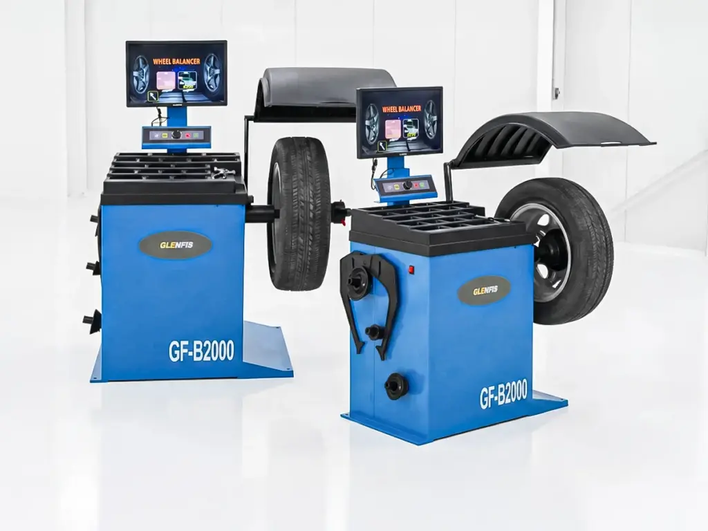
False readings usually trace back to skipped wheel preparation, incorrect centering, wrong dimension inputs, or hardware issues like sensor drift and unstable floors.
Operator Input and Wheel Preparation Issues
The balancer calculates corrective weights from the physical mass it detects and the geometry the operator provides. When technicians skip basic setup steps, the machine processes flawed data.
- Wheel contamination: Leaving dirt, rust, or old adhesive weights on the wheel creates false readings before the machine even starts.
- Mounting errors: Using the wrong cones or clamping the wheel off-center shifts the assembly’s center of mass during rotation.
- Data-entry mistakes: Wrong rim dimensions or the wrong balancing mode force the machine to solve for incorrect geometry.
Machine Calibration and Environmental Factors
Even with careful wheel preparation, the balancer itself can introduce error. The equipment relies on sensitive sensors that need a stable environment and routine maintenance to hold accuracy.
- Calibration drift: Sensors move out of specification over time, so technicians run periodic self-calibration to restore accuracy.
- Hardware wear: Worn spindle shafts, damaged position sensors, or failing boards disrupt the spin signal and keep the balancer from reaching a near-zero reading.
- Environmental interference: Running the balancer on an unlevel or unstable floor, or near vibrating machinery, interferes with the measurement cycle.
How Can Buyers Assess a Wheel Balancer’s Measurement Performance?
Testing measurement performance means checking electronic consistency, mechanical mounting stability, and verifiable calibration routines, so you can confirm the balancer delivers accurate weight placement over repeated daily use.
Conducting Repeatability Tests
You need to know whether a balancer gives the same answer twice. A repeatability test isolates whether the sensors or the mechanical mounting is introducing error into the reading.
- Electronic stability check: Mount and spin the wheel, record the reading, then spin again without touching the assembly. If both readings agree within the manufacturer’s stated tolerance, the measurement chain is electronically stable.
- Index (mechanical) check: Without remounting, rotate the wheel 180° on the shaft and spin. The imbalance magnitude should be similar but the heavy-spot angle shifts by ~180°. A systematic deviation points to a worn shaft, bent spindle, or cone runout.
- Remount check: Remove the wheel, clean the mating surfaces, and remount. If readings shift more than the tolerance states, suspect worn adaptors or inconsistent clamping force.
If the heavy spot shifts drastically between remounts, the cause is usually worn centering cones or a damaged shaft rather than the measurement electronics.
Verifying Accuracy and Calibration Procedures
A balancer’s calculation is only as good as its geometric inputs and its calibration baseline. Confirm the equipment holds a stable tolerance after a standard setup.
- Stated resolution and target: Ask what resolution and residual target the manufacturer specifies. Figures you may see quoted—sometimes around ±1 g resolution or a fraction of an ounce per plane—are model-dependent examples, not universal limits.
- Gauge accuracy: Check that distance and width gauges read consistently against a known wheel, since rim condition can shift measured geometry.
- Calibration sequence: Review the routine; a standard procedure uses a reference steel wheel and known test weights (for example, a clip weight of a set gram value).
- Post-calibration test: After calibration, confirm it reads near zero on a balanced wheel and detects weights moved between planes.
Assessing measurement is only part of the picture; our guide to finding reliable workshop-equipment suppliers covers verification beyond the machine itself.
よくある質問
What does a wheel balancer measure?
A wheel balancer measures how the mass of a tire-and-wheel assembly is distributed around its rotational axis. As the wheel spins, internal sensors quantify the radial and lateral forces caused by uneven weight, then factor in the wheel’s geometry—offset, diameter, and width—to convert those forces into a correction weight and a placement angle.
How does a wheel balancer know where to place weights?
It combines the wheel dimensions you enter with live vibration data. As the wheel spins, force sensors track the size and phase of the imbalance, and a position encoder supplies the angle. The microprocessor maps that to the wheel geometry and shows the weight amount and clock position on a digital readout, LED strip, or laser.
What is the difference between static and dynamic imbalance?
Static imbalance is a single heavy spot that causes vertical hop and is corrected in one plane. Dynamic imbalance is uneven mass across both the inner and outer planes, producing a side-to-side wobble as well as hop. Spin balancers correct dynamic imbalance by calculating separate weights for the inside and outside rim.
Can a wheel balancer give an incorrect reading?
はい. Faulty readings usually trace back to how the wheel is mounted: off-center clamping, worn cones, or dirt on the mating surfaces shift the wheel on the shaft, so the machine misreads the imbalance. Wrong parameter entries, worn components, and calibration drift also produce unreliable results.
How often should a wheel balancer be calibrated?
Follow the manufacturer’s guidance and your workload. Busy shops often verify calibration on a recurring schedule, while lighter-volume shops can go longer between checks. Recalibrate promptly whenever the machine is moved, takes an impact, undergoes repair, or begins giving inconsistent readings and calling for ever more weight.
最終的な考え
A dependable wheel balancer is one whose measurement chain you can verify. High-precision sensors, stable mounting hardware, and clean geometry inputs keep technicians from wasting hours chasing weights, and let your team reach an accurate balance within a single mounting. That repeatability—not a headline number—is what protects your daily throughput and margins.
When you compare machines, test them the way you work: check repeatability, confirm the manufacturer’s stated tolerances, and match the sensor technology to your wheel mix and volume. Contact our equipment specialists to review our balancer range and spec the right machinery for your service bays.


