
Choosing between 3D and CCD wheel alignment systems affects setup time, maintenance requirements, and daily workflow. The key difference lies in how they collect data: 3D systems track passive wheel targets with fixed cameras, while CCD systems use electronic measuring heads mounted on the wheels.
This guide compares their measurement architecture, hardware components, data transmission methods, runout compensation, and calibration requirements. Understanding these differences will help you identify which system better fits your workshop layout, service volume, and maintenance capabilities.
How Do 3D and CCD Wheel Alignment Systems Collect Measurement Data?

Camera-and-target 3D systems track passive wheel targets from a fixed structure, while CCD aligners use active electronic measuring heads mounted directly on the wheels.
Sensor Hardware and Optical Tracking
3D and CCD wheel aligners use different hardware arrangements to measure vehicle geometry. In a typical CCD system, technicians attach electronic measuring heads to the wheels. These heads collect angular and positional data close to the wheel and transmit the results to the main computer.
- CCD measuring heads: Depending on the model, these active units may contain optical sensors, infrared emitters, electronic inclinometers, batteries, and communication modules. They measure wheel orientation and establish geometric relationships between the wheels.
- 3D cameras and passive targets: Fixed cameras mounted on a beam or tower observe patterned targets attached to the wheels. The targets contain no electronic measuring components, while the cameras and software calculate their position and movement.
Comparing 3D and CCD Data Acquisition Workflows
CCD systems calculate alignment values from measurements collected by the wheel-mounted heads. Many models use electronic inclinometers to measure tilt and infrared signals to establish relationships between adjacent measuring heads. The processed data is then sent to the alignment computer.
Camera-and-target 3D systems observe all four wheel targets from fixed camera positions. During rolling compensation and steering procedures, the software tracks changes in each target’s position and orientation. It then uses calibrated camera geometry and image processing to calculate toe, camber, caster, and other alignment values.
The table below summarizes the main differences in hardware placement, measurement methods, and calibration requirements.
| Acquisition Area | CCD Wheel Alignment | 3D Wheel Alignment |
|---|---|---|
| Wheel Attachments | Active electronic measuring heads attached to the wheels. | Passive patterned targets attached to the wheels. |
| Primary Measuring Hardware | Optical sensors and electronic inclinometers inside the measuring heads. | Fixed cameras mounted on a beam, tower, or similar structure. |
| Measurement Method | Measures wheel orientation and geometric relationships between the sensor heads. | Tracks target position and movement using calibrated camera geometry and image processing. |
| Wheel-Side Electronics | Normally requires powered electronic components on the wheels. | Passive targets normally require no batteries, cables, or onboard electronics. |
| Calibration Focus | Measuring heads, inclinometers, and related sensor components. | Camera positions, beam geometry, installation setup, and manufacturer-defined system checks. |
How Do Camera-and-Target 3D Systems Work?
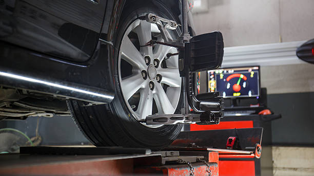
Camera-and-target 3D systems use remote cameras to track passive wheel targets. The software analyzes changes in each target’s position and orientation to calculate wheel alignment angles.
Core Components and System Architecture
Camera-and-target 3D aligners place the primary measuring electronics away from the wheels. Instead of mounting powered sensor heads on each rim, technicians attach passive patterned targets that are observed by cameras positioned around the alignment bay.
The system normally includes three main component groups:
- Camera system: Digital cameras mounted on a beam, tower, or movable structure capture images of the wheel targets. Some models use dedicated lighting to maintain consistent target visibility.
- Passive wheel targets: Wheel clamps hold patterned targets on each wheel. The targets contain no batteries or onboard measuring electronics, although their surfaces, mounting condition, and positioning must remain within the manufacturer’s requirements.
- Computer and alignment software: The system identifies target patterns, processes their movement, and converts the captured data into wheel alignment measurements.
The cameras must maintain a clear line of sight to all required targets. Installation distance, camera height, lift compatibility, and working clearances vary by model and should be confirmed in the manufacturer’s installation documentation.
The 3D Image Processing and Measurement Cycle
After the targets are installed, the system captures alignment data through a short sequence of vehicle movement and optical tracking.
- Rolling compensation: The vehicle is rolled through the distance specified by the manufacturer so the system can identify each wheel’s rotational axis and compensate for mounting or rim runout. The exact procedure depends on the machine and clamp design.
- Target tracking: The cameras record changes in the position and orientation of the target patterns as the wheels roll or steer.
- Coordinate calculation: The software uses calibrated camera geometry and image processing to determine the position and orientation of each wheel.
- Alignment results: The calculated wheel geometry is converted into measurements such as toe, camber, caster, and thrust angle, which technicians can monitor while making adjustments.
The measurement architecture is only one part of the purchasing decision. Workshops should also consider service volume, technician workflow, available space, and expected return on investment when deciding whether a 3D wheel alignment machine is worth the investment.
Buyers who want to compare these features with an available production model can review the GF-A9 3D wheel alignment machine, including its camera configuration, measurement functions, and workshop applications.
Find the Right Wheel Aligner for Your Workshop
How Do CCD Sensor Heads Measure Wheel Angles?
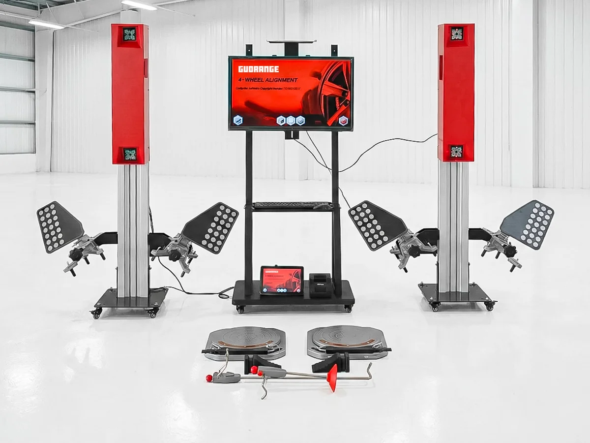
CCD wheel aligners use electronic measuring heads attached to the wheels. Optical sensors, electronic inclinometers, and communication links work together to measure wheel orientation and calculate alignment angles.
How Wheel-Mounted CCD Measuring Heads Collect Data
Technicians attach a measuring head to each required wheel using compatible clamps. Unlike the passive targets used by camera-and-target 3D systems, CCD measuring heads contain active electronic components and normally require batteries or cables.
The internal hardware varies by manufacturer and model. A typical measuring head may include optical sensors, infrared emitters and receivers, electronic inclinometers, processing electronics, and wireless communication modules.
During measurement, the heads determine their orientation and geometric relationship to one another. Many systems use infrared communication between adjacent heads, while electronic inclinometers measure the vertical orientation of each unit. The collected data is processed by the alignment system and transmitted to the main computer.
Converting Sensor Data into Alignment Angles
The alignment software combines the measurements from the wheel-mounted heads to calculate the vehicle’s alignment geometry.
- Toe: The system calculates individual and total toe from the horizontal relationship between the wheel planes and the vehicle’s reference line.
- Camber: Electronic inclinometers help determine each wheel’s inward or outward tilt relative to the vertical reference.
- Caster and steering-axis inclination: Technicians perform a manufacturer-defined steering sweep. The software calculates these values from changes recorded as the wheels turn.
- Runout compensation: Depending on the machine and clamp design, technicians rotate or roll the wheels so the system can identify and compensate for mounting eccentricity or rim runout. Some approved clamp systems may reduce or eliminate this step.
The exact sensor arrangement, number of measuring heads, compensation procedure, and communication method should be confirmed in the model’s technical documentation.
How Is Data Transmitted Between Measuring Units and the Computer?

Data transmission depends on the system design. Camera-based 3D aligners transfer image or processed measurement data, while CCD aligners exchange readings between wheel-mounted heads and the main computer.
3D System Communication Methods
Camera-and-target 3D systems capture images of passive wheel targets and process them either inside the camera unit, through an intermediate controller, or on the main computer. The connection method varies by manufacturer and model.
Common interfaces include USB, Ethernet, Wi-Fi, and other proprietary wired or wireless connections. Buyers should confirm which connection carries raw images, which carries processed measurements, and whether the system requires dedicated network hardware.
CCD System Data Transfer
CCD aligners transmit measurement and synchronization data from their wheel-mounted heads. The communication arrangement depends on the number of measuring heads and the equipment design.
- Communication between heads: Many systems use infrared signals to establish geometric relationships between adjacent measuring heads.
- Connection to the console: Measurement data may reach the main computer through Bluetooth, radio, USB, cables, or a dedicated communication unit.
- Power and mobility: Wireless measuring heads improve movement around the vehicle but require battery charging and dependable signal coverage. Wired systems avoid battery management but introduce cables into the working area.
Buyers should verify communication range, battery runtime, charging requirements, replacement modules, and compatibility with the supplied computer.
How Do Runout Compensation and Calibration Differ?
Runout compensation corrects errors associated with the wheel, rim, and clamp installation. Calibration verifies or adjusts the alignment machine’s measurement system so it remains within the manufacturer’s specifications.
Defining the Purpose of Each Process
Runout compensation addresses eccentricity caused by the wheel, rim, or the way the clamp is mounted. The system observes the wheel through a defined rolling or rotational procedure and separates these mounting effects from the vehicle’s actual alignment geometry.
Calibration applies to the alignment equipment itself. Depending on the architecture, it may involve camera positions, measuring heads, electronic inclinometers, installation geometry, or other manufacturer-defined reference components.
The two procedures are not interchangeable. A calibrated machine can still produce incorrect results if required runout compensation is skipped or performed incorrectly. Likewise, compensation cannot correct a machine that is outside its calibration specifications.
Timing and Operational Workflow
These procedures normally take place at different stages:
- Runout compensation: Performed during vehicle setup when required by the equipment manufacturer. The method may involve rolling the vehicle or rotating individual wheels. Some approved clamp designs may reduce or eliminate this step.
- System calibration: Performed during initial installation, after relevant components are moved or replaced, when verification results fall outside tolerance, or at intervals specified by the manufacturer.
Accuracy, repeatability, and display resolution are separate specifications. Buyers should compare the published figures for each measurement parameter instead of treating values such as 0.01° as a universal accuracy standard.
Which Technical Specifications Reveal the Actual Measurement Architecture?
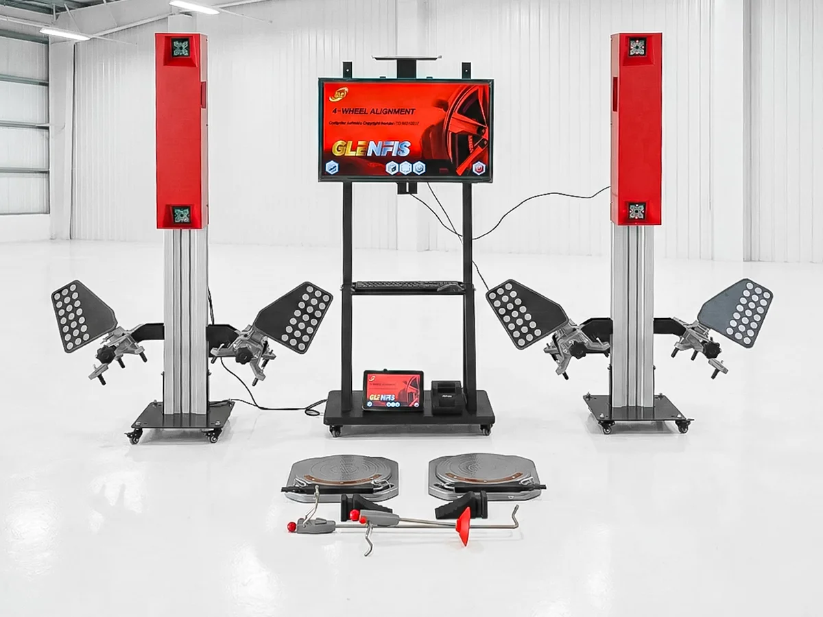
Marketing terms alone may not identify how a wheel aligner collects data. Check the wheel attachments, sensor locations, power requirements, communication methods, and installation instructions.
Hardware Interface: Wheel-Mounted Sensors vs. Passive Targets
The components attached to the wheels provide the clearest indication of the measurement architecture.
- Active measuring heads: A typical CCD specification lists powered electronic heads containing optical sensors, inclinometers, batteries, controls, or communication modules. The number and arrangement vary by model.
- Passive wheel targets: A camera-and-target 3D system uses patterned targets or reflectors without onboard measuring electronics. Fixed or movable cameras observe these targets from outside the wheels.
- External camera structure: A 3D specification should identify the camera beam, tower, pod, or movable structure and explain its required position relative to the vehicle and lift.
Hybrid and specialized systems also exist, so buyers should confirm the architecture in the technical manual rather than relying only on product names.
Operational Specifications and Installation Requirements
The operating procedure and installation requirements provide additional clues about how the machine measures wheel geometry.
- Working space: Camera-and-target systems normally specify camera-to-target distance, field of view, lift compatibility, and required clearances. These values vary by model.
- Runout procedure: Manuals should state whether compensation requires vehicle rolling, individual wheel rotation, or an approved clamp system that reduces the procedure.
- Calibration requirements: Check which components require calibration or verification, what tools are needed, and whether trained technical support is required.
- Measurement performance: Compare accuracy, repeatability, resolution, measurement range, and supported alignment parameters separately.
- Data and reports: Confirm which angular, dimensional, diagnostic, and reporting functions are included. Do not assume that a measurement is exclusive to either 3D or CCD technology.
Toe, camber, caster, and thrust angle are established four-wheel geometry concepts included in the UK government’s automotive service technician occupational standard. However, the measurement range, accuracy, resolution, and supported procedures still need to be verified for each wheel aligner.
Frequently Asked Questions
How does a 3D wheel alignment machine measure wheel angles?
A 3D wheel alignment machine uses high-resolution cameras to track non-electronic, patterned targets clamped to each wheel. As the vehicle rolls or steers, the cameras capture the target movements. The system software applies 3D optical triangulation to calculate the exact coordinates and orientation of each wheel. It then converts this spatial data into standard alignment angles like toe, camber, and caster by comparing the wheel planes against the vehicle centerline and axle planes.
Do 3D wheel aligners use electronic sensors on the wheels?
Conventional camera-and-target 3D wheel aligners normally use passive patterned targets without batteries or onboard measuring electronics. Cameras mounted on a beam, tower, or movable structure observe these targets and send the captured data to the alignment software. Because specialized and hybrid designs also exist, buyers should confirm the architecture in the model’s technical documentation.
How do CCD measuring heads work?
CCD measuring heads attach to the wheels and use electronic sensors to measure wheel orientation and geometric relationships. Depending on the model, they may contain optical sensors, infrared emitters, inclinometers, batteries, and communication modules. The collected data is then transmitted to the alignment computer.
How can I tell whether a wheel aligner is 3D or CCD?
Check what attaches to the wheels. A typical CCD aligner uses powered electronic measuring heads, while a camera-and-target 3D system uses passive patterned targets observed by external cameras. Because hybrid systems also exist, confirm the sensor arrangement, power requirements, and calibration procedure in the technical manual.
Final Thoughts
Neither 3D nor CCD technology is automatically the better choice for every workshop. Camera-and-target 3D systems keep powered measuring electronics off the wheels and can support efficient alignment workflows, while CCD systems offer compact, wheel-mounted measurement hardware that may suit smaller workshops and different budgets. The right choice depends on bay layout, service volume, installation requirements, and maintenance capacity. For a broader comparison of these purchasing factors, read our guide to choosing the best wheel alignment machine for an auto repair shop.
Before ordering, confirm the measurement architecture, working clearances, calibration procedure, software support, and replacement-part availability. Contact our equipment specialists to compare suitable 3D and CCD wheel aligners, review your workshop requirements, and request wholesale pricing.


